Скачать с ютуб Servo Motor Controller & Tester Circuit | 555 Timer Project #12 в хорошем качестве
Servo Motor Controller & Tester Circuit | 555 Timer Project #12
4 года назад
Из-за периодической блокировки нашего сайта РКН сервисами, просим воспользоваться резервным адресом:
Загрузить через dTub.ru Загрузить через ClipSaver.ruСкачать бесплатно Servo Motor Controller & Tester Circuit | 555 Timer Project #12 в качестве 4к (2к / 1080p)
У нас вы можете посмотреть бесплатно Servo Motor Controller & Tester Circuit | 555 Timer Project #12 или скачать в максимальном доступном качестве, которое было загружено на ютуб. Для скачивания выберите вариант из формы ниже:
Загрузить музыку / рингтон Servo Motor Controller & Tester Circuit | 555 Timer Project #12 в формате MP3:
Роботам не доступно скачивание файлов. Если вы считаете что это ошибочное сообщение - попробуйте зайти на сайт через браузер google chrome или mozilla firefox. Если сообщение не исчезает - напишите о проблеме в обратную связь. Спасибо.
Если кнопки скачивания не
загрузились
НАЖМИТЕ ЗДЕСЬ или обновите страницу
Если возникают проблемы со скачиванием, пожалуйста напишите в поддержку по адресу внизу
страницы.
Спасибо за использование сервиса savevideohd.ru
Servo Motor Controller & Tester Circuit | 555 Timer Project #12
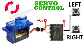
A tutorial on how to make a servo motor controller & tester circuit using 555 timer IC and a few other components. This circuit allows us to manually drive/control any servo motor by pressing buttons or by turning knob of a potentiometer. Link to the project page and circuit diagram: https://elonics.org/servo-motor-contr... Components Required 555 Timer IC Servo Motor 1 PN Diode (I used 1N4148) 2 Momentary Push Button Switches Resistors: 220K, 56K, 10K Capacitor: 100nF Breadboard Few Breadboard Connectors (5-9)V Power Supply (Adapt to Servo voltage) Note: If you wish to control the servo using potentiometer, use a 50K resistor in series with a 1K resistor instead of 56K, 10K resistors and push button switches. Refer to the circuit below for the exact arrangement. This tutorial is a part of 18 video series on Electronic Projects created using IC 555: • 555 Timer Projects on Breadboard With Work... ----------------------------------------------------------------------- For more electronics projects, visit: https://elonics.org/ Like our Facebook page: https://fb.me/elonics/ And don't forget to Subscribe!
Comments